-40%
NanoVNA VNA HF VHF UHF UV Vector Network Analyzer Antenna Analyzer + PC Software
$ 44.34
- Description
- Size Guide
Description
NanoVNA VNA HF VHF UHF UV Vector Network Analyzer Antenna Analyzerbuilt-in battery
+ PC Software
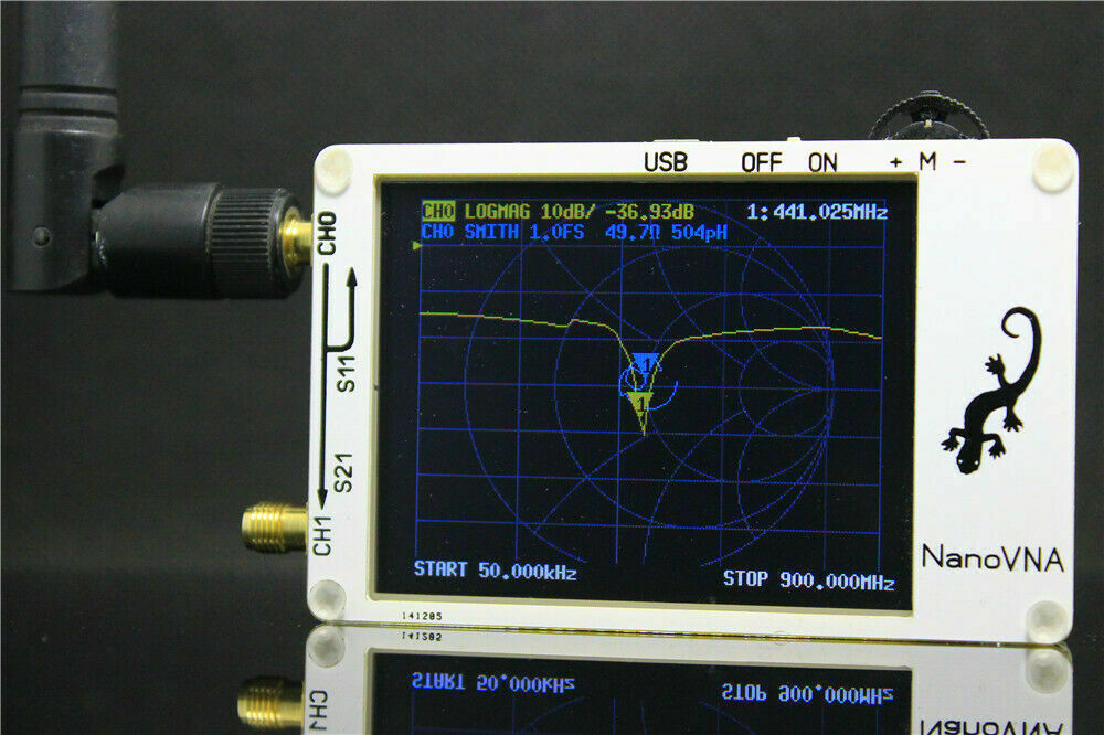
NanoVNA is very tiny handheld Vector Network Analyzer (VNA). It is standalone with lcd display, portable device with battery. This project aim to provide an RF gadget but useful instrument for enthusiast.The default firmware main function is used for antenna performance measurement. If you need more test functions, please update the firmware to "nanoVNA_900_4ch.dfu" Technical data: - Display: 2.8 inch TFT (320 x240) - Power supply: built-in lithium battery - Measurement range: 50KHz-900MHz (default firmware) - RF output: -13dbm (maximum -9dbm) - Port SWR: < 1.1 - Display: 2.8 inch TFT (320 x240) - Size: 54mm x 85.5mm x 11mm - Weight: 63 grams - Full set of accessories: main unit / 1 set, 3 SMA male calibration parts
Basic performance:
● PCB: 50mm x 68mm x 10mm (without connector, lever switch)
● Measurement frequency: 50KHz ~ 300MHz (50KHz -900MHz, enable extended firmware)
● RF output: -13dbm (maximum -9dbm)
● Measurement range: 70dB (50kHz-300 MHz), 40dB (300M-900MHz, enable extended firmware);
● Port SWR: < 1.1
● Display: 2.8 inch TFT (320 x240)
● USB interface: USB tyoe-C communication mode: CDC (serial)
● Power: USB 5V 120mA, can use battery powered, maximum charging current 0.8A
● Number of scanning points: 101 (fixed)
● Display Tracking: 4, Marking: 4, Setting Save: 5
Set the frequency range (STIMULUS>START/STOP or CENTER/SPAN)
Calibration (CAL) Select display format and channel (DISPLAY) Save (SAVE) You can change the display format and channel selection at any time. In the normal test mode, tap the right area of the screen or press the dial switch to call up the menu.Tap the screen or turn the wheel switch to select a menu item. The unit is in the initial state (no data is stored in 0) Scan range 50KHz - 300MHz (50KHz -900MHz if it is 900M firmware) Track 1: LOGMAG CH0 (reflection) (default firmware) Track 2: SMITH CH0 (reflection) (default firmware) Track 3: LOGMAG CH1 (pass) (requires flash nanoVNA_900_4ch.dfu firmware) Track 4: CH1 stage (pass) (requires flash nanoVNA_900_4ch.dfu firmware) -Mark 1: Open Not calibrated. We will test before shipment and calibrate the directly connected SMA port. The calibration data is stored in state 0 and the next time it is turned into state 0 data. calibration: Calibration with the specified mechanical calibration requires three loads: open, short and load.The calibration data is saved as user calibration data. It can be saved to status 0 and can be automatically loaded at the next power on. It can be saved to status 1-4 and can be loaded via the RECALL menu. Click the CAL→CALIBRATE menu to open the calibration interface, then connect open, shortAnd load three loads, and click on the menu corresponding to calibrate port 0. This unit comes with a simple calibration kit. For the male calibration unit, S is short-circuited (SHORT), L is loaded with (LOAD) 50 ohm load, and internal is open (OPEN). For the female calibration part, the short circuit (SHORT) is used for short-circuiting the solder on the back, the (LOAD) 50 ohm load is applied to the two 100 ohm resistors, and the open circuit (OPEN) is used for the open circuit.Isolation calibration of port 1 requires two load loads to connect port 0 and port 1 for best isolation. Usually the user has only one set of calibration loads for port 0. When there is only one load calibration piece, simply connect the loadcalibration piece. To port 1, port 0 remains open and then press ISOLN tocalibrate. The pass-through calibration for port 1 requires only the RF cableto be used to connect port 0 and port 1 and then press the THRU menu tocalibrate.After the calibration is completed, press the DONE button to pop up thesave interface to select the desired state for saving.After the calibration is completed, you can connect the three calibration pieces to port 0 again.Check whether the calibration is correct through the SMITH diagram. The correct calibration should be: when the connection is open, the curve should be concentrated on the far right side of the SMITH circle. When the connection is short, The curves should all be centered on the leftmost side of the SMITH circle. When connecting LOAD, the curves should be concentrated in the middle of the SMITH circle. Connect port 0 and port 1 using an RF cable and see that the S21 curve error should not exceed 0.5 dB. If the calibration data is found to be abnormal, it should be recalibrated. If calibration has been applied, the CAL status is displayed on the left side of the main screen. C * is the state in which the unsaved calibration value is applied (this value will disappear after restart). C0 ~ C4 0 to 4 means that the saved calibration value has been applied to one of the save locations. Save is not saved When you save by operation, it changes to this state. C Each character shown below indicates that the following calibration term has been applied: D: Direction, R: Reflection Tracking, S: Source Match, T: Transmission Tracking, X: Isolation, C* Note: nanoVNA_300_4ch.dfu nanoVNA_900_4ch.dfu Both firmwares have the above C* functions. The factory default firmware cancels this feature!
Select the display channel and display type:
Through the menu's DISPLAY→TRACE item, you can choose to open or close the corresponding display channel.The color of the channel is the same as the color of the interface curve. The display channel of the last operation is the active tracking channel.
The FORMAT, SCALE, CHANNEL operations of the menu
are valid for this display channel.
The display type can be modified by DISPLAY→FORMAT in the menu, DISPLAY→SCALE can
Adjust the scale of the scale, and DISPLAY→CHANNEL
can select the measured port.
Set the frequency range:
There are three main and frequency range related
parameters: start frequency, center frequency and stop frequency.
The relationship between them is satisfied:
Fcenter = (fstart +fstop )/2
Fspan= fstop- fstart
Where fspan is the span.
The center frequency of the current screen is set by
STIMULUS→CENTER in the menu, and the values of the center frequency and the span are displayed on the left and right sides of the grid, respectively. Click in the lower right corner of the pop-up setting value screen to pop up the soft keyboard and input the corresponding frequency value through the soft keyboard.
Pay attention to the following points during use:
Modifying the center frequency will modify the start frequency and the end frequency under the condition that the span is kept constant (except when the start frequency or the end frequency reaches the boundary). When the zero span is used, the start frequency, center frequency, and termination frequency are the same.At this time, port 0 can be used as a signal source of a fixed output amplitude, but it is necessary to pay attention to the use of the clock signal generator S5351 as the most signal source, and the output signal is square. Wave, containing large odd harmonics. Set the frequency range through the menu's STIMULUS→SPAN, and display the center frequency and span value respectively on the left and right sides of the grid. Click on the lower right corner of the
pop-up setting value screen to pop up the soft keyboard and input the corresponding frequency value through the soft keyboardPay attention to the following points during use:Modifying the span will automatically modify the start and stop frequency of the spectrum analyzer.When the span setting exceeds the maximum value, the spectrum analyzer enters full span mode.When zero span is used, the start frequency, center frequency, and end
frequency are the same.Set the starting frequency through the menu STIMULUS→START, and display thevalues of the starting frequency and the ending frequency on the left and right sides of the grid respectively. Click on the lower right corner of the pop-up setting value screen to pop up the soft keyboard and input the corresponding keyboard through the soft keyboard. Frequency value.
Pay attention to the following points during use:
Modify the starting frequency to modify the center frequency and span value together before the span reaches the minimum value (parameter modification caused by the span change, see the description of the span),
continue to increase after the span reaches the minimum value. Change the termination frequency.
When zero span is used, the start frequency, center frequency, and end frequency are the same.
The frequency is terminated by the STIMULUS→STOP setting of the menu, and the values of the starting frequency and the ending frequencyare displayed on the left and right sides of the grid respectively. Click on the lower right corner of the pop-up setting value screen to pop up the soft keyboard and input the corresponding keyboard through the soft
keyboard. Frequency value.
Pay attention to the following points during use:
Modifications in the termination frequency cause changes in span and center frequency, which can affect other system parameters.See the introduction in the “Sweeping” section for details.
When zero span is used, the start frequency, center frequency, and end frequency are the same.
Menu)
● DISPLAY
○ TRACE
■ TRACE 0 (Default firmware)
■ TRACE 1 (Default firmware)
■ TRACE 2 (requires flash nanoVNA_900_4ch.dfu firmware)
■ TRACE 3(requires flash nanoVNA_900_4ch.dfu firmware)
○ FORMAT
■ LOGMAG
■ PHASE
■ DELAY Not implemented.PC host computer
provides Group delay function)
■ SMITH
■ SWR
■ MORE
^POLAR(
^LINEAR
○ SCALE
■ SCALE/DIV
■ REFERENCE POSITION
■ ELECTRICAL DELAY (Not implemented)
○ CHANNEL
■ CH0 REFLECT
■ CH1 THROUGH
● MARKER
○ SELECT
■ 1
■ 2
■ 3
■ 4
○ MARKER→START
○ MARKER→STOP
○ MARKER→CENTER
○ MARKER→SPAN (Not implemented)
● STIMULUS
○ START
○ STOP
○ CENTER
○ SPAN
○ CW FREQ
● CAL
○ CALIBRATE
■ OPEN
■ SHORT
■ LOAD
■ ISOLN
■ THRU
■ DONE
■ SAVE
○ RESET
○ CORRECTION
● RECALL/SAVE
○ 0 (Default)
○ 1
○ 2
○ 3
○ 4
● CLOSE
Shipping
Item will be shipped out within 2 business days after receipt of your payment, we ship the item through hongkong Air mail or China Post. We Ship to Worldwide, but Italy, Nigeria, Brazil will take long delivery time .
Before buying, Please make sure your address is correct. Or not, please correct it before payment
Ship to worldwide from Hong Kong within 12-24 hours after payment completed received, and will give you the tracking number asap. sometimes we will send it by flat post air mail if just one low price order.Hope you understand.
we advise shipping by DHL or EMS,and we have gave a discount for you,you can received it in 4-9 business days.
it takes about 15-30days usually if shipping by CHina/Hong Kong post air mail
Payment
We ONLY accept payment by Paypal.
All payments must be received within 7 working days after auction has ended. Non-paying bidders will be reported to ebay.
Feedback
If you have any questions or comments about our products or policies, please contact us by emails with your purchased item number.
You also can contact us by leaving us an eBay message,we will be responded within 24hours.
Customer satisfactory is most important to us. If you have a problem or question regarding your transaction please contact us before leaving any type of feedback.
Negative feedback does not solve anything. We are always willing to work things out, thank you!
Return Policy
Refunds are only offered for defective products reported within 7 days upon receipt
Buyers need to return the defective item for the replacement at his own cost. Item must be returned by registered airmail to our requested address.
We do our best to serve each and every customer the best we can.
if you need more items,we can provide you a wholesales price,you can contact us by message or email.


